
Preliminary Concepts: Binary Arithmetic
Adding
in Binary
Simple Transistor Operations
Transistors are devices in a computer chip that, like a light switch, can either be on (1) or off (0). Putting these switches together, we can represent a number. For example, to represent the number 5 (base-10), we would use three switches in a row: on, off, on. That is, a 101 in binary is a 5 in base-10. We can also use switches to perform simple operations, or actions on our numbers.
First, for practice, let's add two numbers in base-10 (you've been doing this since elementary school):
| 1 | ←carried digits | |
| 15 |
||
| + |
17 |
|
| |
||
| 32 |
||
You probably first added the 5 to the 7 in the right-most column and came up with 12. This doesn't fit in one column, so the 2 is written in the answer's rightmost column, and the 1 is "carried" to the next column. Next, you add 1 + 1 + 1 for a total of 3, which is written in that column of the answer.
Now let's see how a similar problem is done in base-2. First, there are only four possible combinations that could occur in the right-most column of our arithmetic problem:
| 0
+ 0 |
= | 0 |
| 0
+ 1 |
= | 1 |
| 1
+ 0 |
= | 1 |
| 1
+ 1 |
= | 10 |
Note that 1 + 1 = 10 (which is two, but written in binary—that is, a 1 in the 2s column and a 0 in the 1s column). If we need to add 1 to 1, then we will write down the 0 in that column and carry a 1 to the next column to the left. Now let's try another problem:
111 |
←carried digits | |
| 101 |
||
| + |
111 |
|
| |
||
| 1100 |
||
We work our way from right to left as follows:
- Add the rightmost column, 1 + 1 = 10 (that's two, written in binary). This doesn't fit in one column, so write down the 0 and carry the 1 to the left.
- Add the next column over: 1 + 0 + 1 = 10. Write down the 0 and carry the 1 to the left.
- In the third column from the right, add 1 + 1 + 1 = 11 (that's three, written in binary). Write down the 1 and carry the 1 to the left.
- In the leftmost column, all we have is the 1 that we carried. Write it down, and we have the final answer.
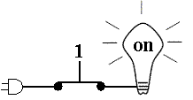
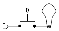
We can use transistor switches not only to represent numbers but also to perform operations on those numbers, such as adding, subtracting, and so forth. Transistor switches can be controlled by an electrical signal. For example, if the control signal is a 1, then the switch turns on, and if the control signal is a 0, then the switch turns off. Look at this example. On the left, we see that a 1 turns the switch on, connecting the plug to the light bulb, so the bulb turns on. On the right, we see that a 0 turns the switch off, disconnecting the plug from the bulb, so the bulb turns off.
 |
 |
We can put two of these switches in a row, and use them to decide when to turn a light bulb on. In the example below, if both switches get a control signal of 1, then the bulb will turn on. If either switch (or both) get a control signal of 0, then the bulb will not turn on. This is an example of an AND gate. The AND gate turns on the bulb only if the first input AND the second input are both 1.

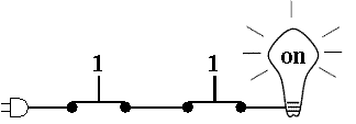
You use the AND function all the time in order to make decisions. For example, if you are in an automobile parked in a garage, you decide when to put your foot on the accelerator by checking if the garage door is open AND if the car is in reverse. If either of these conditions is false, i.e., a logic 0, then you do not put your foot on the accelerator. When both conditions are true, i.e., a logic 1, then we press the accelerator.

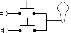
If we put connect the switches so that they both connect to the light bulb directly as shown below, then we have a logical OR function, where if either switch is turned on with a 1, then the light bulb will turn on. Notice that this is not an "exclusive OR"—if both switches are turned on, the bulb still turns on.
![]() Advanced
Advanced
![]()
![]()
These pages were written by Steven H. VanderLeest and Jeffrey Nyhoff and
edited by Nancy Zylstra
©2005 Calvin University (formerly Calvin College), All Rights Reserved
If you encounter technical errors, contact computing@calvin.edu.